Gryazovets – Vyborg: cross-country gas pipeline
 Overview
 Photos
November 7, 2012

Through the example of the Yuzhno-Russkoye field we gave you an idea of how gas is produced. But gas production is half the voyage. It needs to be delivered to consumers. Today we'll show you the way of building gas trunklines that cross our country in every direction, evolving all together into the Unified Gas Supply System of Russia.
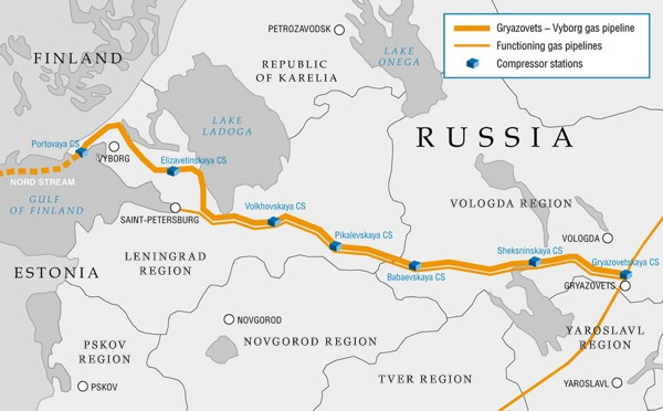
We shot our photo essay in August when construction of the second string of the Gryazovets – Vyborg gas trunkline was in progress. This string is 680 kilometers long (as it was built with loops, its length is shorter than the overall length of the gas pipeline which is 917 kilometers). This gas pipeline is designed for securing gas supplies to Nord Stream as well as to consumers in the Northwestern Russia. The gas pipeline runs across the Vologda and the Leningrad Regions.
The design capacity of the gas pipeline stands at 55 billion cubic meters per year. In addition to the linepipe, 7 compressor stations have been built, including the Portovaya CS, a unique facility in the global gas industry. There is no similar facility anywhere in the world. The throughput exceeds 366 MW, therefore enabling gas to travel 1,200 kilometers along the Baltic Sea bottom.
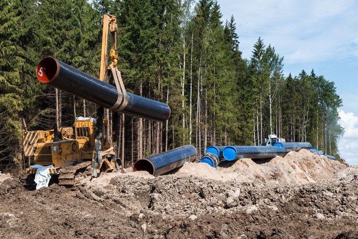
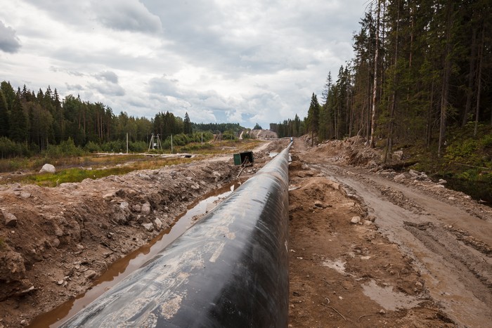
A great part of the gas pipeline runs through forests and swamps. The gas pipeline travels nearly fifty kilometers across hard rocks in the Vyborg District of the Leningrad Region. It’s worth mentioning that any gas trunkline has no easy sections during its construction. At every stage there are nuances, peculiarities, twists and turns. Gas pipelines' strings pass through any climatic zone in our country, from permafrost to the warm southern regions.

When we were shooting this photo essay, the linear part of the gas pipeline, located in the Leningrad Region, was nearing completion. We saw two sections: the first one runs through tough rocks near Vyborg, and the second – the micro-tunnel being constructed under the Saimaa Canal.
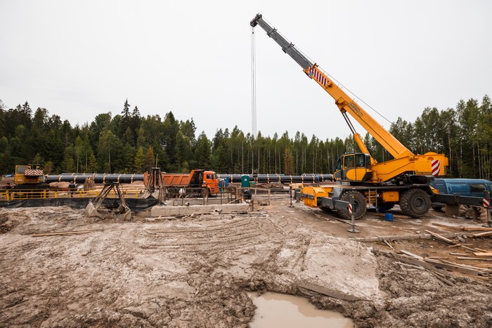
As a matter of fact, construction of a single gas pipeline takes place in very different geographical environments, and it's more likely to say that an installation crew comes to a new working place every day. That's why the whole construction site is expected to be mobile and operational everywhere, providing new linear meters of a just welded pipe.
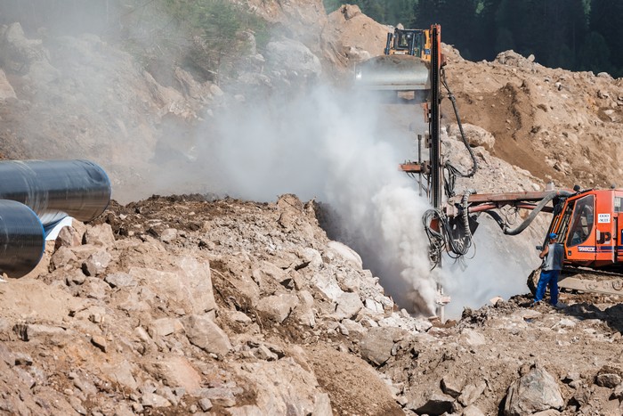
Trenching in a regular ground doesn't usually cause any problems, but doing the same job in a swamp makes it far more difficult, and as for rock excavation – it requires a drill and blast tunneling method. Meaning that along the route of a future trench some holes are drilled – so called blast-holes, afterwards filled with a blasting charge.
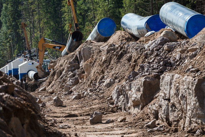
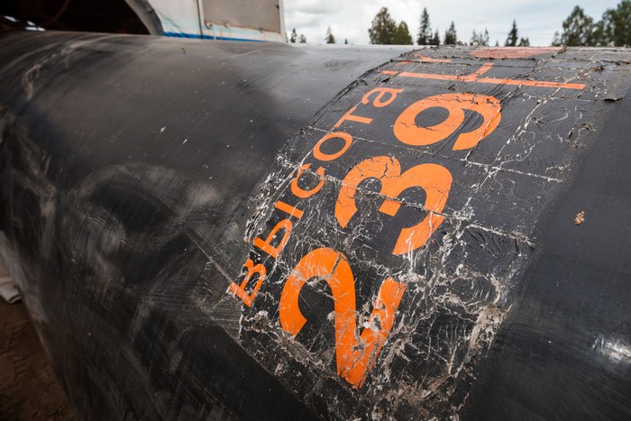
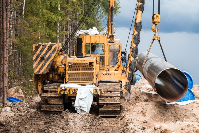
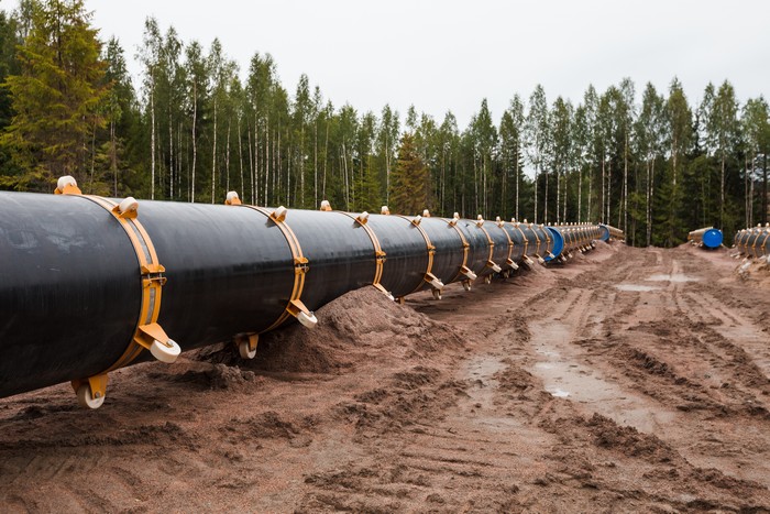
Then the rest of rock stones are removed from the trench, its bottom is leveled out, and a sand bed is arranged just before pipe laying. At the same time, with the trench installation, pipes are laid alongside the route. By the way, these pipes are produced by one of the modern workshops, Vysota 239, focused on manufacturing large-diameter pipes, at the Chelyabinsk Pipe Rolling Plant. Gazprom also collaborates with other domestic producers – in summer 2012 the Company signed the Sci-Tech Cooperation Agreement with the United Metallurgical Company, Severstal, TMK and the above mentioned Chelyabinsk Pipe Rolling Plant.
Talking about the Company's cooperation with Russian pipe producers, we'd like to point out that Gazprom together with its partners carry out the Sci-Tech Cooperation Programs, particularly focusing on development and production of new types of pipes that our Company needs for implementing its projects in the Yamal Peninsula, Eastern Siberia and the Far East.
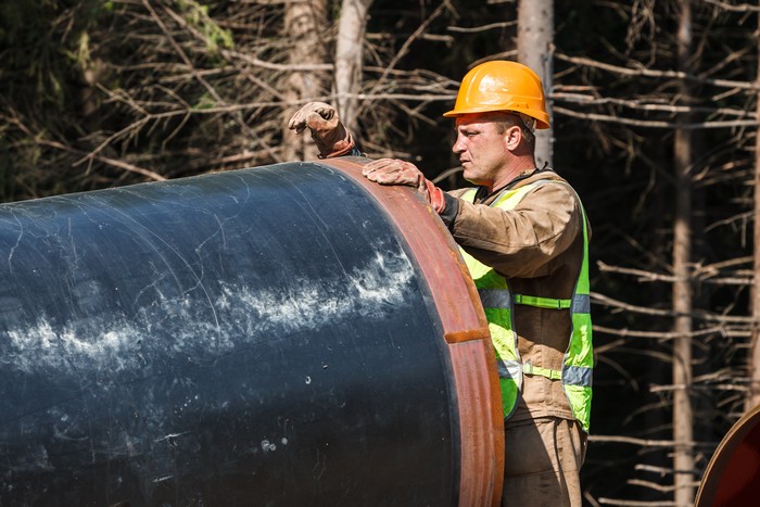
These people call themselves ‘the linemen’ – they are involved in building only the linear part of the gas pipeline, and leave gaps in the places of road crossings and engineering services. Other experts deal with these sections: breakaway crews and bore crews. They are engaged in construction of crossings that are laid under railways and motor roads, as well as water crossings.
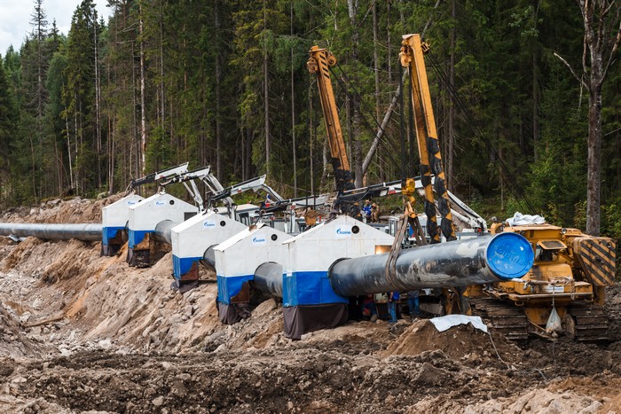
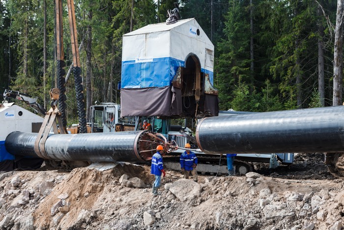
Let's have a look at the main stages of the gas pipeline's linear part welding. On the photo you may see a mobile unit: a mobile welding column and a system for automated and machine orbital welding of pipes.
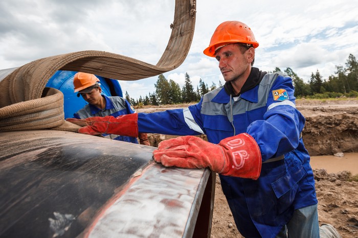
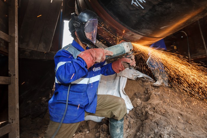
The process starts with preparing pipe joints being rubbed and revealing shiny metal underneath, by using an ordinary angle grinder.
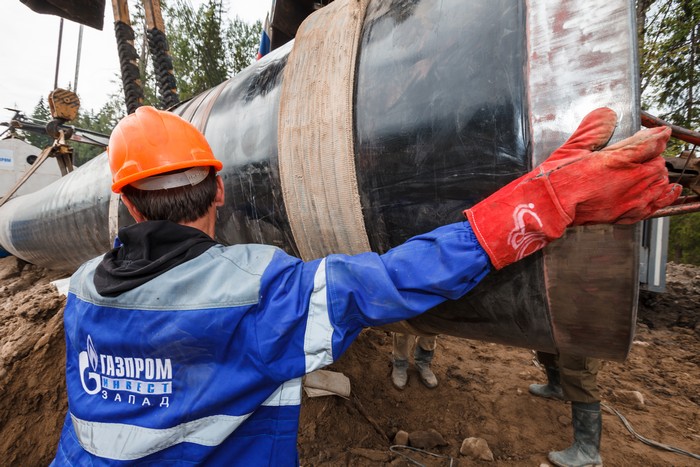
Afterwards, a pipe clamp – a device that centers edges of a new pipe with a welded section of the gas pipeline – is initialized. The movement of alignment clamps, spread symmetrically around a circle, helps fix pipes against each other and in the meantime leave a gap, which is essential for root welding, between the edges.
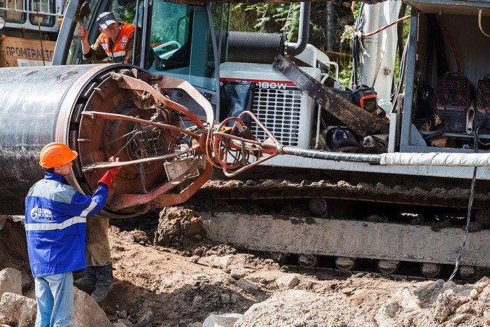
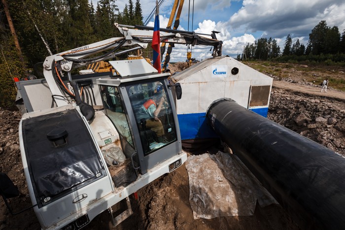
After the pipes preparation process is completed, a pipe layer adjusts pipes to the installation position with fabric slings – straps that prevent the original insulated coating from damage.
Have a close look at the track of the pipe layer – sometimes even tough metal crashes in the stony land of the construction site.
In this place, above the pipeline string, a water stream (that was temporarily drawn off) will run, and in this section the pipes with a greater wall thickness are used, as outlined in the project.
Now it's time for pipes installation and edges alignment using the above mentioned pipe clamp.
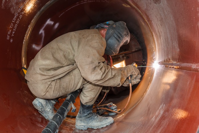
After the installation process is completed, a welding station is placed above the joint. The station is a booth, and inside there is some welding and ancillary equipment as well as individual lighting and air conditioning. Besides, operations can be carried out inside all the year round, preventing precipitation from falling and wind from affecting the welded joint.
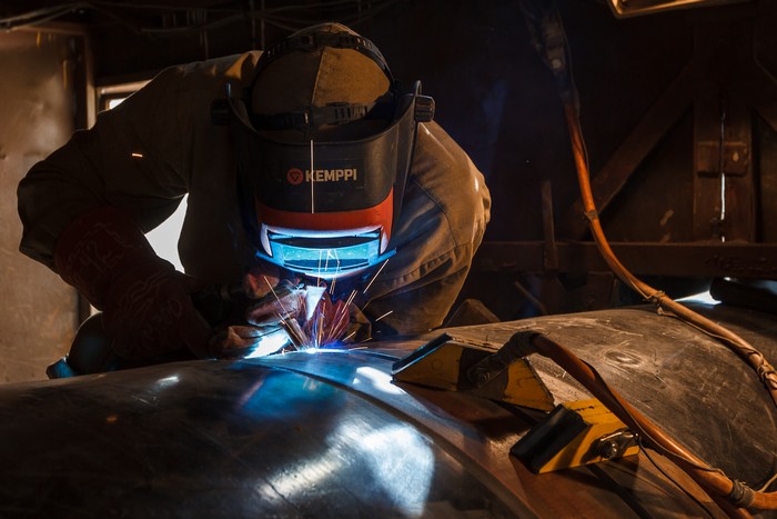
At the station, a mechanical method is used to make the first weld, i.e. the root weld, in shielding gas environment. This method increases welding speed by over three times versus the manual method and improves the quality of the welded joint.
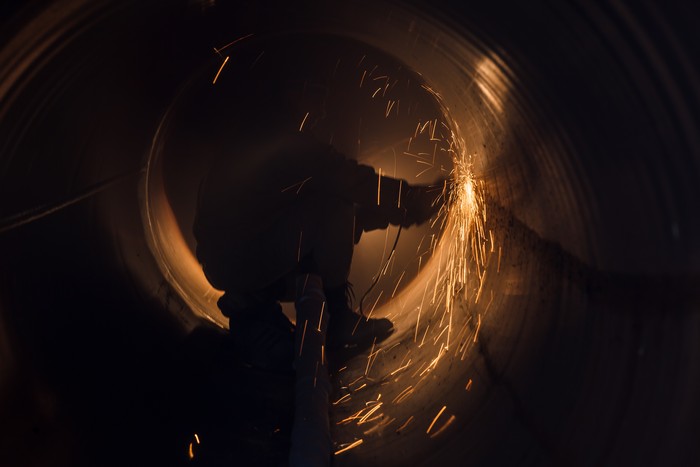
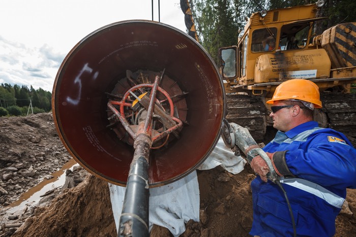
After the root layer is done, the shaped turning roll is inspected from the inside, and defects are eliminated if necessary.
Spaces where allowable offset of the abutting edges occur are rewelded – as this mission would be impossible to accomplish only by means of using the inner pipe clamp.
From the outside the root layer of the weld is prepared for automated welding.
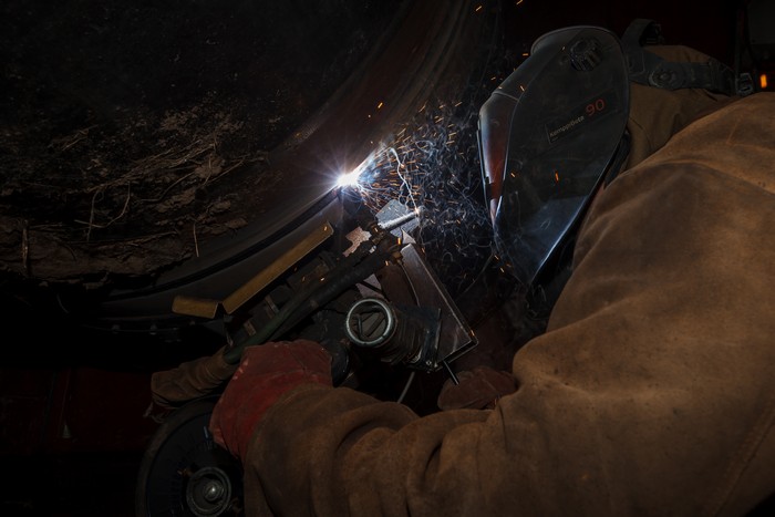
Then the automated orbital welding heads are installed on the joint (one head on the each side). Welding of filling and facing layers goes in a fully automated mode – a welding operator monitors only a welding carriage moving along the joint and controls penetration to secure a high quality filling of the welded joint. Usually one double run is carried out in each booth. This complex includes four booths.
The gas pipeline’s section is ready assembled. After construction is completed, all welded joints are tested through the non-destructive inspection technique.
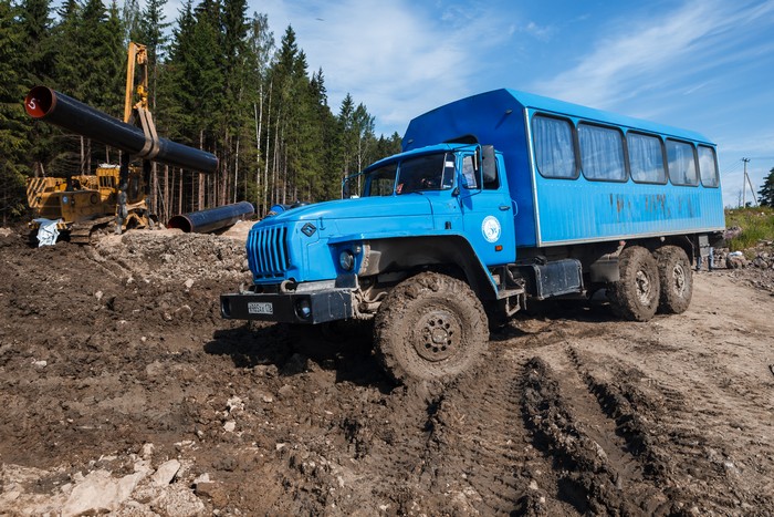
It’s time for a break now. All construction workers live in Vyborg, and a crew bus drives them to the working site. Lunch dishes are delivered by the said bus which also serves people as a canteen.
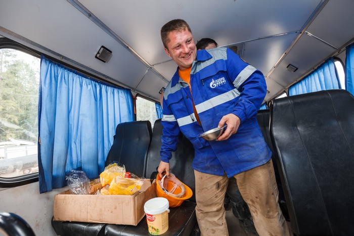
Most of these men have been Gazprom’s employees for many years, they built gas pipelines in every part of Russia. We’d better not to bother them and leave the men to have their lunch. Let’s see another part of the construction site.
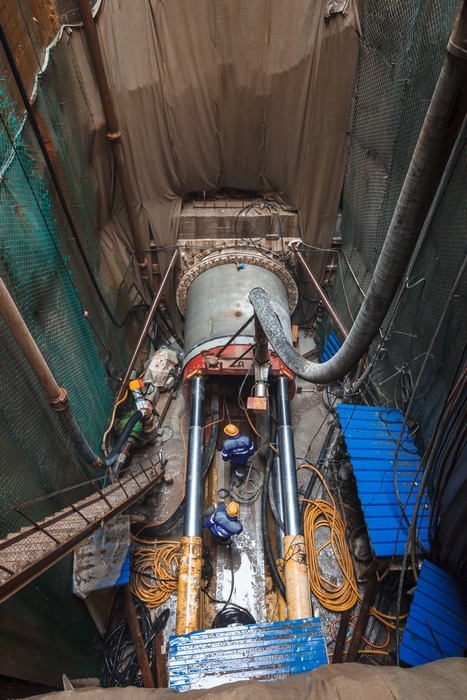
We are heading inland across the Karelian Isthmus. The next section – the micro-tunnel being constructed under the Saimaa Canal, near the Palli Lock. Before reaching the Saimaa Canal, the gas pipeline has crossed a river in the similar way just once – in 2009 the builders of the Gryazovets – Vyborg gas pipeline constructed a micro-tunnel under the Neva River.
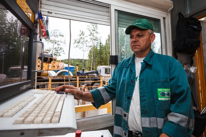
The Herrenknecht tunnel boring machines are used in construction of the micro-tunnel that goes under the Canal. The process is similar to the big tunnel construction, only the jacks that push a shield forward are located not on it, but in the installation room at the depth of 21 meters. A supervisor works in the special overground booth – there is just no room for him on the shield.
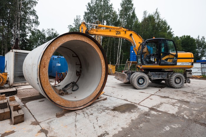
The tunnel is assembled from reinforced concrete pipes, plant manufactured, with a 3-meter length and a 2.5-meter outer diameter.
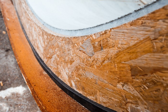
The liner design is tailored to resist the maximum earth load and is also waterproof. As pipe sections are rammed, a special-purpose grease is input between the liner and the formation (construction clearance) and ease the movement of the fabricated tunnel.
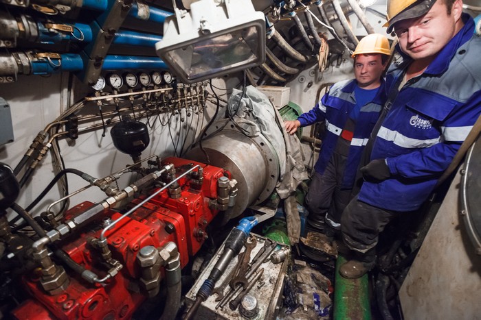
As for the shield itself, this is a real underground starship fitted with all kinds of equipment, including navigation devices – to secure the pipe laying is aligned with the planned route.
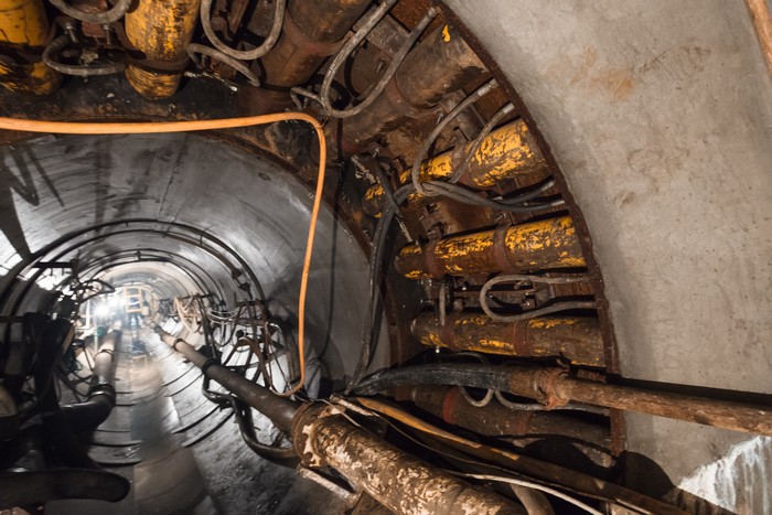
The jacking unit located in the entry pit can’t continuously press through the whole tunnel, i.e. 250 meters. For this reason, some additional jacking sections are installed between every 50 or 70 meters, therefore securing the shield and the liner are thoroughly rammed.
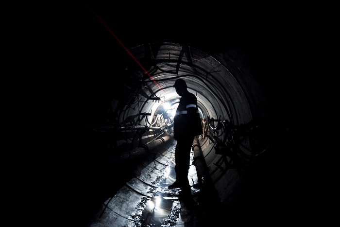
The laser theodolite in the jacking unit ensures precise shield movement along the route. A laser ray falls on a special board situated in the tunnel face, and beam deflection can show the direction of the complex deviation.
On the opposite bank a ready-to-go pipeline string has been welded and waiting to be rolled into the micro-tunnel.
In our photo essay it’s impossible to show you in detail every feature of gas pipelines construction. But we did try to reveal some secrets of this hard work. We’d like to thank Gazprom Invest Zapad for assistance in planning the photo shoot. See you soon!